1. User Manual for ESP-F
| Date: | 2018-01-26 |
|---|
This section provides the user manual for ESP-F.
1.1. Introduction
The WiFi module ESP-F is manufactured by using a high-performance chip ESP8266EX, which can be seen in Fig. 1. This small chip is encapsulated an enhanced Tensilica’sL106 diamond series 32-bit kennel CPU with a SRAM. Thus, ESP8266 has the complete function Wi-Fi function; it not only can be applied independently, but can be used as a slaver working with other host CPU. When ESP8266 is applied as a slaver, it can start from the onboard Flash. The built-in high-speed buffer is not only benefit to improve the system performance, but optimize the store system. In addition, ESP8266 can be used as Wi-Fi adapter by SPI/SDIO or I2C/UART interface, when it is applied to other MCU design.
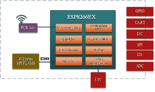
ESP-F Module Structure
The ESP-F module supports the standard IEEE802.11 b/g/n/e/i protocol and the complete TCP/IP protocol stack. User can use it to add the WiFi function for the installed devices, and also can be viewed as a independent network controller. Anyway, ESP-F module provides many probabilities with the best price.
Parameters for ESP-F are listed as follows.
Paramters for ESP-F
| Types | items | Parameters |
|---|---|---|
| WiFi | Frequency Scope | 2.4G~2.5G(2400M~2483.5M) |
| Transmit Power | 802.11b: +20 dBm | |
| 802.11g: +17 dBm | ||
| 802.11n: +14 dBm | ||
| Receiving sensitivity | 802.11b: -91 dbm (11Mbps) | |
| 802.11g: -75 dbm(54Mbps) | ||
| 802.11n: -72 dbm(MCS7) | ||
| Antenna | PCB onboard antenna | |
| Hardware | CPU | Tensilica L106 32 bit MCU |
| Perpherl | UART/SDIO/SPI/I2C/I2S/IR control | |
| GPIO/ADC/PWM/SPI/I2C/I2S | ||
| Working voltage | 2.5V ~ 3.6V | |
| Working current | Average current: 80 mA | |
| Working temperature | -40°C ~85°C | |
| Environment temperature | -40°C ~ 85°C | |
| Size | 16mm x 24mm x 3mm | |
| Software | Wi-Fi mode | Station/SoftAP/SoftAP+Station |
| Security mode | WPA/WPA2 | |
| Encryption type | WEP/TKIP/AES | |
| Update firmware | UART Download/OTA (by internet) | |
| Software develop | Non-RTOS/RTOS/Arduino IDE etc. | |
| Network protocol | IPv4, TCP/UDP/HTTP/FTP/MQTT | |
| User configuration | AT+command/cloud sever/Android/iOS APP |
PINs Definition
PINs definition of ESP-F can be shown in the following.
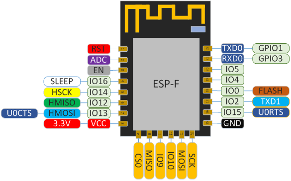
Pins definition for ESP-F Module
Selection of Working Mode
Working mode and definition of pins:
| Mode | GPIO15 | GPIO0 | GPIO2 |
|---|---|---|---|
| UART download | low | low | high |
| FlashBoot mode | low | low | high |
Function Definition of Module Pins
| Num | Pin | Type | Function |
|---|---|---|---|
| 1 | RST | I | Reset the signal outside (enable with low), Reset module |
| 2 | ADC | I | A/D pin. Input voltage 0~1V, value: 0~1024 |
| 3 | EN | I | high level:chip work;low level:chip closes with small current. |
| 4 | IO16 | I/O | deep sleep/wakeup |
| 5 | IO14 | I/O | GPIO14; HSPI_CLK |
| 6 | IO12 | I/O | GPIO12;HSPI_MISO |
| 7 | IO13 | I/O | GPIO13;HSPI_MOSI;UART0_CTS |
| 8 | VCC | P | Module working voltage: 3.3V |
| 9 | CS0 | I/O | GPIO11; SD_CMD; SPI_CS0 |
| 10 | MISO | I/O | GPIO7; SD_D0, SPI_MSIO |
| 11 | IO9 | I/O | GPIO9; SD_D2 PIHD; HSPIHD |
| 12 | IO10 | I/O | GPIO10; SD_D3;SPIWP; HSPIWP1 |
| 13 | MOSI | I/O | GPIO8; SD_D1;SPI_MOSI1 |
| 14 | SCLK | I/O | GPIO6; SD_CLK; SPI_CLK |
| 15 | GND | P | GND |
| 16 | IO15 | I/O | GPIO15; MTDO;HSPICS;UART0_RTS |
| 17 | IO2 | I/O | GPIO2; UART1_TXD |
| 18 | IO0 | I/O | GPIO0;SPI_CS2 |
| 19 | IO4 | I/O | GPIO4 |
| 20 | IO5 | I/O | GPIO5 |
| 21 | RXD | I/O | GPIO3; used to build in Flash as UART Rx |
| 22 | TXD | I/O | GPIO1; used to build in Flash as UART Tx |
1.2. Shape and Size
Shape and size for this module can be shown as follows. Its size is 16mm*24mm*3mm, and the Flash is 4M bytes (32Mbits), together with the following picture.
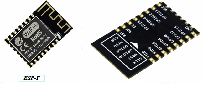
ESP-F Module
Size of ESP-F module
| Length | Width | Height | Pin | Distance between pins |
|---|---|---|---|---|
| 24.5mm | 14mm | 3mm | 4x2 | 2.54mm |
1.4. Power Consumption
Power Consumption
|Tx802.11b, CCK 11Mbps, POUT=+17dBm | - | 170 | - | mA | +-------------------------------------+-------------+-------------+-----------+-----------+ |Tx802.11g, OFDM 54 Mbps, POUT =+15dBm| - | 140 | - | mA | +————————————-+————-+————-+———–+———–+
- Modem-Sleep mode can be used for the case that CPU is always working, e.g., PWM or I2S etc. If WiFi is connected and no data is to transmitted, in this case, WiFi modem can be closed to save power energy. For example, if at DTIM3 status, keep asleep at 300ms, Then, the module can wake up to receive the Beacon package within 3ms and the current being 15mA.
- Light-Sleep mode can used for the case that CUP can stop the application temporally, e.g., Wi-Fi Switch . If Wi-Fi is connected and there is no data packet to transmitted, by the 802.11 standard (e.g., U-APSD), module can close Wi-Fi Modem and stop CPU to save power. For example, at DTIM3, keep up sleeping at 300ms, it would receive the Beacon package from AP after each 3ms, then the whole average current is about 0.9mA.
- Deep-Sleep mode is applied to the case that Wi-Fi is not necessary to connect all the time, just send a data packet after a long time (e.g., transmit one temperate data each 100s) . it just need 0.3s-1s to connect AP after each 300s, and the whole average current is much smaller 1mA.